| Avmount Vibro Dampers : Type AVM | ||||||||||||||||||||||||||||||||||||||||||||||||||||||||||||||||||||||||||||||||||||||||||||||||||||||||||||||||||||||||
|
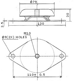
Avmount Vibro Dampers are highly efficient yet economical vibration and shock isolators. This product is EXCLUSIVELY manufactured by us. You can use them for vibration of compressors, diesel generators, fans and motors as well as for the protection of mounted equipment from external vibration or shock. Being of extremely robust design, these isolators are particularly suitable for rugged conditions and give trouble-free and continued service. Their life is generally equal to that of the machinery or plant which is mounted on them. Avmount Vibro Dampers Type AVM in addition to isolating machinery and structures from vibration and shock, provide a means sitting stabilisation so that the floor areas are undisturbed with no need for bolting or grouting in. machinery is left free-standing and thus can be re-sitted with ease. To meet certain requirements, however, holes are provided in the base plate. Machinery mounted on our dampers is isolated both actively and passively. The machinery is isolated actively in the sense that the machine which is a source of vibration is so isolated that the incidence of transmission of vibration to the floor upon which it rests is reduced to an extent, and passively in the sense that the machine which would be affected adversely by external sources of vibration is now insulated from them. Avmount Vibro Dampers Type AVM have a bottom friction pad bounded to the bottom of the mounting and hence there is no necessity of adding another friction pad. Dimensions of Vibro Dampers (Type AVM)
Technical Specifications of Vibro Dampers (Type AVM)
d = deflection at rated load Fn = Natural frequency at rated load and deflection fd = Disturbing frequency F = Rated load/mount Note: It is essential that all mounts deflect equally so that the system has a single natural frequency and not different natural frequencies at each point.
Type AVM 120/280
Type AVM 275/650
Applications of Vibro Dampers (Type AVM)
Mounting Procedure for Vibro Dampers (Type AVM) 1. Obtain the weight and the Centre of Gravity of the assembly to be mounted. 2. If this is not readily available, obtain weights and respective Centres of Gravity of the individual units which make up the mounted mass. For instance, the engine, radiator, alternator, flywheel, base frame, etc. from a D. G. set. 3. Determine the position of the Centre of Gravity of the assembly by reference to two vertical planes at right angles to each taking moments of the separate units about these datum planes and dividing the respective sum of these by the total weight of the assembly. 4. Determine the disturbing frequencies which are usually primary and/or secondary orders of the slowest speed of the machine. 5. Decide on the minimum amount of isolation required. Normally aim for more than 80%. 6. With reference to the basic vibration chart, assess the deflection required on the mounts which when under load will operate at the desired natural frequency.
7. Decide on the type and number of mounts required after
reference to the static spring rate characteristics which
indicate the load/deflection and load capacity details, bearing
the following points in mind: 8. Fix the mounting positions around the machine so that each mount will be equally loaded. This is achieved by ensuring that the algebraic sum of the horizontal centre distances of the mountings about the Centre of Gravity equals to zero. This exercise must be carried out in both directions. Long spans between mounting points should be avoided and normally limited to 3 to 4 feet although this figure is obviously dependent upon the structural rigidity of the machine or the sub-base on which the driver and driver units should be fixed. 9. If it is not possible to distribute the mounts symmetrically about the Centre of Gravity it will be necessary to take moments to assess the load reactions at the most convenient mounting points. This is needed to determine a modified mounting stiffness requirement to give uniform deflections on all mounts. Click here to find the right kind of mount for your machine
|
||||||||||||||||||||||||||||||||||||||||||||||||||||||||||||||||||||||||||||||||||||||||||||||||||||||||||||||||||||||||
 Avmount
Vibro Dampers are designed to use the isolating media, rubber
in this case, both in compression and in shear. It is bonded
to metal during vulcanisation such that the design makes the
mounting have an equal stiffness in all directions. The mounting
can be used for mobile applications also, since the base of
the mounting is provided with holes for attachment to the
chassis. It also has a friction pad bonded to the bottom of
the base for proper fixation of the machine to the floor in
case of stationary applications. Hence no bolting is necessary
under these conditions.
Avmount
Vibro Dampers are designed to use the isolating media, rubber
in this case, both in compression and in shear. It is bonded
to metal during vulcanisation such that the design makes the
mounting have an equal stiffness in all directions. The mounting
can be used for mobile applications also, since the base of
the mounting is provided with holes for attachment to the
chassis. It also has a friction pad bonded to the bottom of
the base for proper fixation of the machine to the floor in
case of stationary applications. Hence no bolting is necessary
under these conditions. 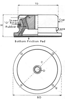
 Installation
of equipments on VIBRO DAMPERS is the modern method of installing
equipment which must be protected from shock and vibrations
which are inherent in many environments.
Installation
of equipments on VIBRO DAMPERS is the modern method of installing
equipment which must be protected from shock and vibrations
which are inherent in many environments.